

How to Map Underground Utilities Before You Build
Learn how to map underground utilities with records, field detection, and 3D data capture to reduce risk, protect crews, and plan projects with confidence.
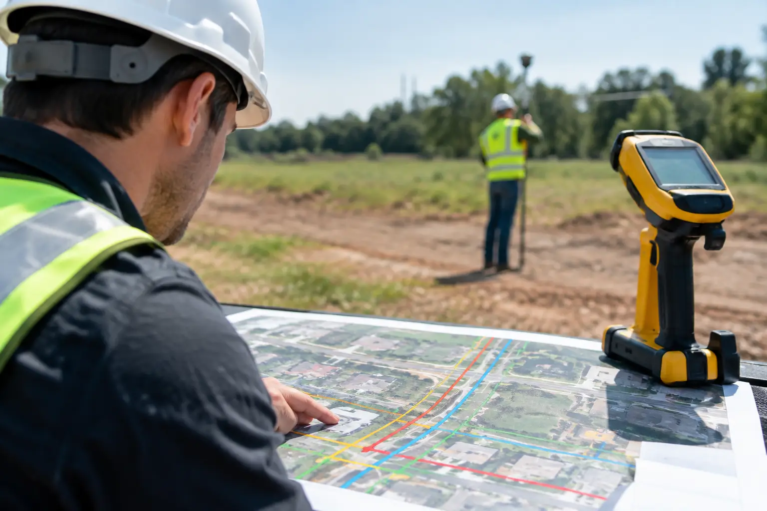
Learn how to map underground utilities with records, field detection, and 3D data capture to reduce risk, protect crews, and plan projects with confidence.
How to Map Underground Utilities Before You Build
A utility strike can stop a project long before construction begins. It can damage critical services, put crews at risk, trigger costly redesigns, and create disputes over what was known before work started. Knowing how to map underground utilities means building a defensible picture of the site, not simply marking a few lines on the ground.
For developers, contractors, facility managers, and design teams, that picture should support better decisions from concept planning through construction and long-term asset management. The most reliable approach combines existing records, field detection, survey control, targeted verification, and a digital deliverable that the project team can actually use.
How to map underground utilities: start with a clear purpose
The required level of detail depends on what the project team needs to do. A feasibility study for a commercial site may need a broad understanding of utility corridors, connection points, and major constraints. A road excavation, foundation design, or plant upgrade requires far greater confidence in the location and depth of individual services.
Define the scope before mobilizing equipment. Establish the site boundary, the utilities of concern, the required positional accuracy, the coordinate system, and the final outputs. This avoids a common problem: collecting data that looks useful on a plan but cannot be trusted for design, excavation, or handover.
The scope should also distinguish between visible above-ground assets and buried infrastructure. Meter cabinets, valve boxes, manholes, hydrants, electrical cabinets, and utility poles can provide vital clues, but they are not proof of an underground route. A manhole may connect to multiple lines, and a visible service entry does not confirm the exact path or depth of a buried cable.
Build the desktop record before going to site
Begin with every available source of existing information. This can include utility-owner plans, as-built drawings , civil drawings, previous survey files, BIM models, site photographs, maintenance records, drainage layouts, and historical aerial imagery. On operating facilities, maintenance teams often hold practical knowledge that never made it into formal drawings.
Treat these records as evidence, not certainty. Utility plans may be outdated, schematic, based on a different coordinate system, or incomplete after years of extensions and repairs. In older industrial, hospitality, and urban sites, undocumented private utilities are especially common. A record search is still essential because it directs the field investigation and reveals where uncertainty is highest.
At this stage, identify likely conflicts. For example, a proposed lift pit, retaining wall, drainage run, or new telecom duct route may cross areas where records suggest multiple services. These locations should receive priority during field verification.
Establish survey control that connects every dataset
Utility mapping loses value when different teams work from different reference points. The surveyor, designer, contractor, and facilities team need one coordinated spatial framework. Establish site control using the project’s approved coordinate system and vertical datum, then capture detectable utilities and surface assets against that control.
This matters when combining underground findings with drone mapping , LiDAR scans, topographic surveys, or Scan-to-BIM documentation . A utility route that is accurate in isolation can still be operationally misleading if it is offset from the building model, proposed structure, or finished ground levels.
For complex commercial sites, a coordinated 3D environment makes conflicts easier to understand. Teams can see whether a pipe passes beneath a loading bay, runs beside a foundation, or crosses a proposed access route. That is more useful than relying on separate PDFs that require manual interpretation.
Use the right field detection method for each utility
No single technology finds every buried utility. The strongest field workflow uses complementary methods and records how each feature was identified.
Electromagnetic locating is effective for conductive utilities such as metallic pipes, power cables, and tracer wires. A technician can use a direct connection, induction, or a signal applied through accessible points such as valve boxes and manholes. Results can be highly useful, but signal bleed, congested corridors, poor grounding, and disconnected tracer wire can affect interpretation.
Ground-penetrating radar, or GPR, can help identify subsurface anomalies, non-metallic pipes, voids, and utility crossings. Its performance depends heavily on site conditions. Dry, sandy soil often produces better results than wet clay, reinforced concrete, or highly congested ground. GPR should be used as part of an investigation, not presented as a guarantee that every buried service has been found.
Visual inspection adds another layer of evidence. Opening accessible chambers, tracing duct entries, reviewing pipe labels, and inspecting service risers can clarify connections that a locator cannot confirm from the surface. Where safe and permitted, CCTV inspection may assist with drainage and sewer networks.
Field markings should identify the suspected utility type, route, and confidence level. The team should avoid converting uncertain findings into overly precise-looking CAD lines. Clear uncertainty is far safer than false confidence.
Verify critical routes through safe exposure
When a utility affects excavation, structural design, or a high-risk work area, non-destructive verification is often the right next step. Vacuum excavation or carefully controlled test pits can expose a utility to confirm its horizontal position, depth, material, size, and condition.
This process, often called potholing, is not necessary everywhere. It should be targeted where the consequences of being wrong are high: beneath proposed foundations, at utility crossings, beside energized electrical lines, near gas infrastructure, or along new drainage and trench routes.
Verification also helps resolve conflicting signals. A detected line may be abandoned, while an active service could be installed nearby. Exposing selected points allows the project team to calibrate the rest of the interpretation and make more confident design decisions.
Local notification and permitting requirements remain essential. In the United States, projects typically coordinate with the relevant one-call system before excavation. Elsewhere, the equivalent utility-owner notification process and local safety rules apply. A mapping survey supports safe planning, but it does not replace mandatory clearance procedures or site-specific excavation controls.
Capture depth, quality, and confidence – not just location
A useful underground utility map records more than colored linework. Every mapped feature should carry attributes that explain what the team knows and how it knows it. These may include utility type, material, diameter or cable count where available, depth, detection method, surveyed position, date captured, owner, and confidence classification.
Confidence is particularly valuable. A route traced from reliable electromagnetic detection and verified at test pits should not carry the same status as a line inferred from an old drawing. Design teams can then focus further investigation where it is needed instead of applying the same contingency across an entire site.
Depth must be handled carefully. Surface elevation changes, sloping ground, and variable cover can make a single depth notation misleading. Where vertical information is critical, record the relevant datum and whether the measurement refers to the top of the utility, centerline, or invert level. For drainage networks, invert levels and flow direction can be as important as the route itself.
Turn utility findings into a coordinated digital asset
The final deliverable should match the way the client will use the information. For a development project, that may mean a georeferenced CAD survey and a utility constraints plan for the engineering team. For an industrial facility, it may include a coordinated 3D model that supports maintenance, expansion planning, and contractor briefings.
This is where LiDAR mapping, 3D spatial capture, and Scan-to-BIM workflows add operational value. Surface conditions, plant rooms, external structures, access zones, and visible service assets can be captured as a precise spatial context around the underground data. The result is a coordinated environment where teams can assess clearances, communicate constraints remotely, and reduce reliance on fragmented documentation.
For property portfolios and facilities with frequent upgrades, the utility model should remain a living record. New installations, verified depths, alterations, and decommissioned services should be updated after each project. The initial survey becomes more valuable over time because it reduces repeat investigation and preserves knowledge when staff, consultants, or contractors change.
Common mistakes that create avoidable risk
The first mistake is treating utility-owner drawings as construction-ready truth. They are a starting point, not final evidence. The second is requesting a utility survey without defining its intended use, which can leave a design team with insufficient accuracy or missing attributes.
Another frequent issue is collecting field data without tying it to formal survey control. This creates misalignment between underground findings and proposed designs. Finally, teams sometimes deliver a static plan without recording confidence, method, or limitations. That may look complete, yet it gives the next user no way to judge where further verification is required.
The best utility mapping work makes uncertainty visible, focuses effort where risk is highest, and delivers data in a format that improves decisions. Before the ground is disturbed, a coordinated record of what is known, suspected, and verified can protect people, budgets, schedules, and the long-term value of the asset.